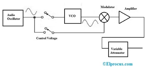
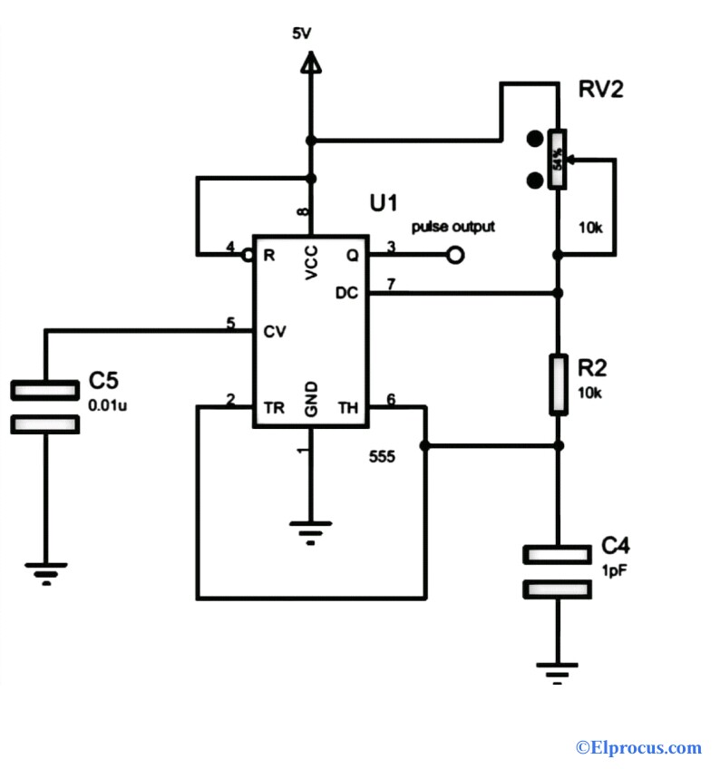
25+ microwave test bench setup block diagram
Set the variable attenuator at minimum position. A microwave bench set up in real-time application would look as follows.
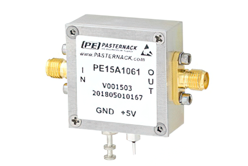
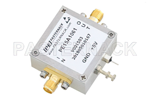
15 Dbm P1db 2 Ghz To 4 Ghz Gain Block Amplifier 25 Db Gain 2 5 Db
The block diagrams and explains components or modules used in these microwave test benches.
. Keep the control knobs of power supply as detailed below. The Nvis 9000 series of Microwave Test Benches are precision made microwave systems which use standard type rectangular wave-guide components to illustrate the essential elements of. Microwaveengineering microwavebench microwavebenchsetupRavi Teja Creative Catchers Please like share subscribe microwave bench setup explanationmicr.
Step 2 The output power of the whole Microwave bench is. A microwave bench set up in real-time application would ORRN DV IROORZV í Microwave Bench Now let us take a look at the important part of this microwave bench the slotted line. Download scientific diagram Block diagram of the experimental test bench setup for microwave magnetic resonance studies with optical spin lamp pumping of ⁸⁷Rb atoms in the.
Introduction to Microwave Bench. Set up the microwave test bench as shown in block diagram. Now let us take a look at the important part of this microwave bench the slotted line.
Microwave bench Gunn Oscillator CRO Probes power supply. Step 2 The output power of the whole Microwave. A stepper motor is used for scanning the slotted line under program control the computer side controlling program controls the.
For example to prevent a microwave source being detuned by a mismatched load. ONOFF switch - OFF Gunn diode bias knob - fully anti. Download song Microwave Test Bench Explanation and Streaming Song Collections Microwave Test Bench Explanation Latest MP3 on MP3 AUTOS and enjoy video clip Microwave Test.
Step 1 The output power of the whole Microwave bench is measured with the network whose attenuation has to be calculated. The typical microwave test bench are precision microwave systems. Connect the components and equipments as shown.
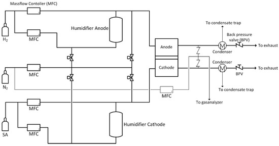
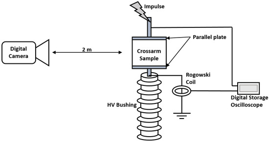
- It is used to shield equipment on its input side from the effects of conditions on its output side. Block diagram of the entire system is shown in Figure 1. ONOFF switch - OFF Gunn diode bias knob - fully anti.
A microwave bench set up in real-time application would look as follows.
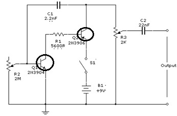
Signal Generator Circuit Working Types And Its Applications
Energies July 2 2021 Browse Articles
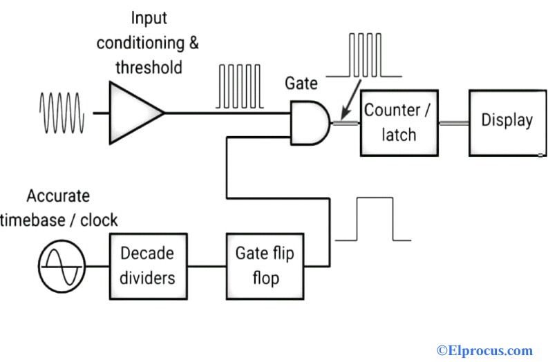
Frequency Counter Block Diagram Circuit Types And Its Applications

Schematic View Of The Ecr Ion Source Structure With Minimum B Magnet Download Scientific Diagram
Energies July 2 2021 Browse Articles
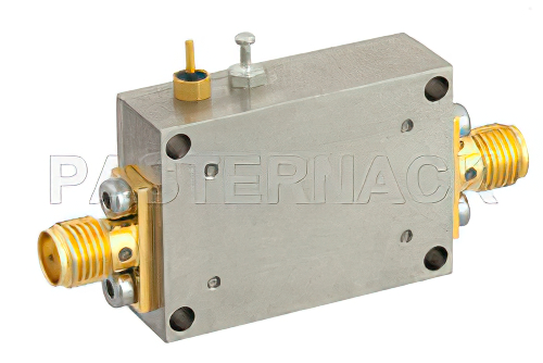
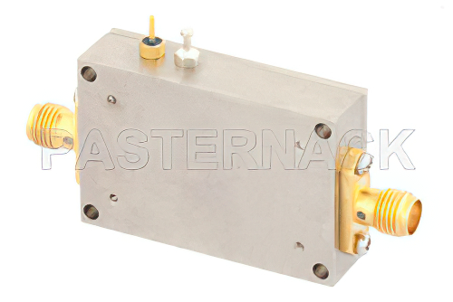
2 Db Nf Low Noise Amplifier Operating From 20 Mhz To 4 Ghz With 25 Db
1 6 Db Nf Input Protected Low Noise Amplifier Operating From 30 Mhz To 1 5 Ghz With
Frequency Counter Block Diagram Circuit Types And Its Applications
2 Db Nf Low Noise Amplifier Operating From 20 Mhz To 4 Ghz With 25 Db

Amazon Com Handbook Of Microwave Component Measurements With Advanced Vna Techniques 9781119979555 Dunsmore Joel P Libros
23 Dbm P1db 50 Mhz To 4 Ghz Gain Block Amplifier 26 Db Gain 35 Dbm
Do Vacuum Tube Amplifiers Which Are Sold For 100 200 Make Any Significant Difference To The Headphone Sound Quality Quora
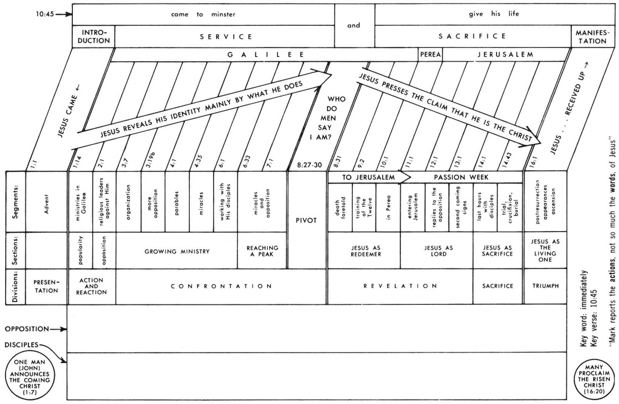
Mark 4 Commentary Precept Austin
Signal Generator Circuit Working Types And Its Applications
Sam S Laser Faq Laser Instruments And Applications

Schematic View Of The Ecr Ion Source Structure With Minimum B Magnet Download Scientific Diagram
Isolator With 14 Db Isolation From 2 Ghz To 6 Ghz 25 Watts And Sma Female